Related inFORMS Blog Articles
Metal TIMs 101: Chapter 2
Folks: a short time ago, I posted "Metal TIMs 101: Chapter 1" with Jon Major. Now it is time for Chapter 2!
Read MoreMetal TIMs 101: Chapter 1
Folks, Dr. Ron: For my next several posts, I would like to chat with Indium Corporation’s metal thermal interface materials (TIMs) Product Manager Jon Ma...
Read MoreLiquid Metal Experimentation with Miloš Lazić (Part 4)
We are back today to finish our conversation with Miloš Lazić to find out how he became interested in liquid metals.
Read MoreLiquid Metal Experimentation with Miloš Lazić (Part 3)
Yesterday, in Part 2 of our interview, Miloš mentioned how using a hybrid solid/liquid TIM provides benefits over thermal grease. Today we discuss the challenges of working with liquid metal, and how to address these issues.
Read MoreLiquid Metal Experimentation with Miloš Lazić (Part 2)
In yesterday’s post, Miloš and I discussed what he’s been working on in the lab. Today we answer a question that impacts our TIM customers.
Read MoreFeatures & Benefits
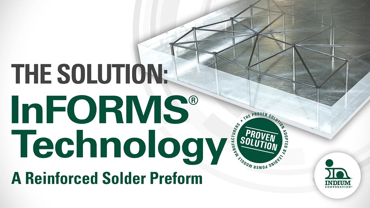
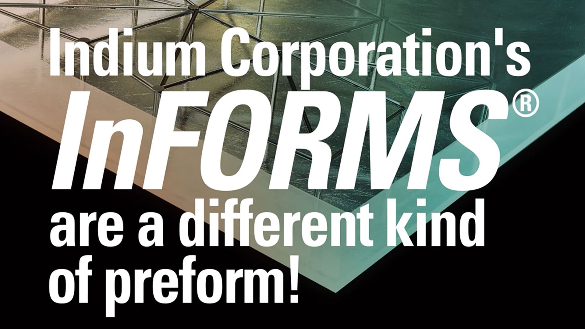
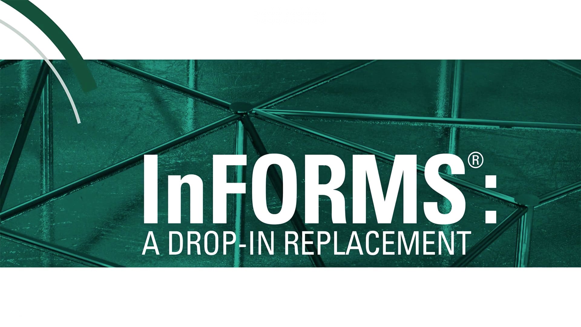
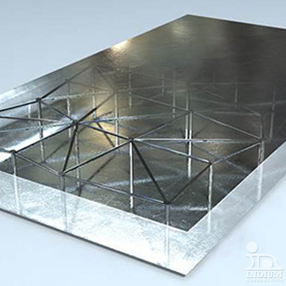
InFORMS® provides improved strength and a more consistent bondline thickness. This maximizes the thermal and mechanical reliability of the solder joint. InFORMS® can be manufactured in a wide variety of shapes, including rectangles and discs, as well as custom shapes to suit specific application requirements. InFORMS® also come in the form of ribbon for automated assembly.
- Improves strength of the solder joint
- Consistent bondline thickness
- Maximizes thermal and mechanical reliability
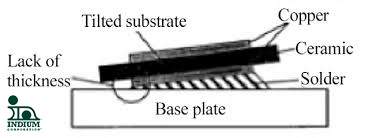
Results
In testing, InFORMS® have shown to improve the reliability of the interconnect to at least 3500 thermal cycles, which exceeds the typical reliability specification of 1500 passive thermal cycles for -55/+150 °C.
Product Advantages
InFORMS® offer dramatically improved handling when compared to conventional solder alloys or indium-based sheets, foils, ribbons, or large preform materials. InFORMS®® also offer increased tensile and compressive strength via the substrate materials, while retaining the unique attributes of the outer layer metal (e.g., the softness, ductility, and other advantages of indium).
Applications
InFORMS® provide engineers with an enhanced material for the development of new, or the improvement of existing, applications. They can be used in cryogenic or vacuum seals, EMI and RFI shielding, ground straps, stand-offs, thermal mismatch devices, or backplane assembly washers. While a number of metals may be used, indium metal should be considered for many applications because of its unique attributes. For example, indium readily wets glass, quartz, and glazed ceramics. When compared to conventional solders, indium-based solders significantly reduce scavenging and leaching of gold and other precious metals.
Substrates and Outer Layer Metals
InFORMS® can be produced from a wide range of metal and non-metal substrates, depending on the needs of the application. Please contact our Technical Support Engineers if you would like us to work with you to develop samples for experimentation, including special substrate materials, layer thicknesses, or outer layer metallizations.
In applications where the metal meets in the substrate matrix, metals used on outer layers may be dissimilar, as long as they are compatible with each other. Where the application does not require cold welding of the outer layers, the layers may also be dissimilar. In either case, compatibility with the substrate material must be considered in applications development. Contact Indium Corporation at techsupport@indium.com for advice or additional questions.
Summary
Save time and money with InFORMS® – an innovative solution that maintains uniform solder bondline thickness.
- Reduce voiding
- Improve reliability
- Enhance soldering performance
Dimensional Specifications
InFORMS® can be produced in a variety of standard and custom shapes. Dimensional tolerances can be held to those normally specified for standard solder preforms, but may vary depending on the part size, thickness, substrate, and outer layer materials. Please contact us if you have special requirements.
Standard Configurations
| Solder Preform Requirements | |||
|---|---|---|---|
| Description | Standoff (Microns) | Part Dimensions (x and y) (Millimeters) |
Part Dimensions (z) (Microns) |
| LM04 | 100 | >10 per side | >150 |
| LM06 | 150 | >10 per side | >200 |
| LM08 | 200 | >10 per side | >250 |
| SM04 | 100 | 2.5-10 per side | >150 |
| ESM03 | 75 | .75-2.5 per side | >125 |
| ESM02 | 50 | .75-2.5 per side | >100 |


