Folks,
Dr. Ron: For my next several posts, I would like to chat with Indium Corporation’s metal thermal interface materials (TIMs) Product Manager, Jon Major, about metal TIMs. Jon, can you tell us a bit about yourself; your technical background, how you got connected to Indium Corporation, how you became interested in TIMs etc.?
Jon: I’ve always been passionate about product development, engineering, materials, and manufacturing. I was fortunate enough to start my career in Silicon Valley, working with the brightest engineers on the planet; I had the opportunity to work on several groundbreaking products, such as the first iPad Air, the first cloud-based smartphone called the “Sidekick”, the first internet connected radio, and several other mobile devices, as well as an IoT platform for connected vehicles.
Jon: Thermal management was always considered at the design level, especially when dealing with consumer products. At Indium Corporation, I have the opportunity to dive deep, not only with the materials themselves, but how they perform with various surfaces, pressures, under varying warpage conditions, and how long they will survive under different use conditions. Our principal thermal engineer recently developed an in-house thermal test vehicle that provides the representative environment for examining performances of thermal interface materials. It’s rather fascinating! I was happy to be a part of a project that enables us to give our customers valuable data on how metal-based TIMs perform under varying conditions.
Dr. Ron: Jon, can you explain briefly why metal TIMs are needed and how they work?
Jon: As integrated circuit (IC) technology has advanced, the amount of heat generated by a high-performance IC is staggering, sometimes exceeding 1,000 watts when the IC is only slightly bigger than an inch (2.5 cm) on one side. The IC typically needs to operate at less than 100°C or its life will be too short. Without TIMs to conduct the heat away from the IC and to the heat-sink, this goal would be impossible.
(Figure 1 shows a schematic of an IC with two TIMs to conduct the heat to the heat-sink.)
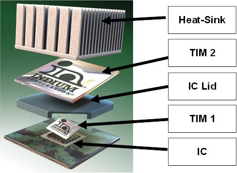
Figure 1. TIM1 conducts heat from the IC to the IC package lid. TIM2 conducts heat from the IC package lid to the heat-sink.
Jon: In the past, polymeric (traditional) TIMs, gels, and other non-metal TIMs were used. In some applications, they are still used today. The most common was thermal grease, which has been used for many decades. Thermal grease has a carrier that is almost like Vaseline®. The carrier is loaded with conductive particles. The thermal grease is then applied where the metal TIMs are in Figure 1. Thermal grease has two shortcomings. One is that its thermal conductivity is not sufficient to meet higher-heat fluxes generated by high performance computing (HPC), AI, accelerated process unit (APU), and graphics processing unit (GPU) trends. The other is that the on/off cycles of electronics can cause “pump-out.” Pump-out occurs when the thermal grease is pumped-out from the space that it occupies to conduct heat away from the IC. With the thermal grease pumped out, it can no longer perform its function.
Jon: This is where metallic based TIMs come in. They can provide the lowest thermal resistance and be customized for package-specific needs. They also do not typically experience pump-out.
Jon: With the advancement of HPC, we see customers having additional challenges due to die thinning and warpage, thermal cross talk (heat from neighboring components), and various other design challenges. Demand for metal-based TIMs continues to grow as they can solve many of these challenges and provide the performance and reliability required in high-power density applications.
Jon: While the primary purpose of a TIM is to help transfer heat from a hot surface to a cold one, there are other attributes to consider in certain applications (e.g. ease of assembly, reliability, sustainability). Metal-based TIMs can be classified as soldered (reflowed), compressible (non-reflowed), liquid based (liquid metal TIM), or as a phase change TIM. Phase change TIMs are designed to change phase when a certain temperature is achieved. We will cover all of these metal TIMs in future postings.
Jon: Metal TIMs have the advantage of having some of the highest bulk thermal conductivities of TIM materials, but it is important to recognize that bulk thermal conductivity alone is not the sole criteria for the selection of a TIM. Thermal contact resistance, or interfacial resistance, typically dominates overall TIM thermal resistance. Therefore, high surface wetting, to minimize thermal contact resistance, is a critical TIM performance criterion.
Dr. Ron: As I understand it, TIM1 is usually a solder TIM. Can you explain how they work?
Jon: TIM1 is commonly referred to as the interface between the backside of a die and the underside of an integrated heat spreader (IHS) and component cap. A soldered TIM (sTIM) at this interface is the “Cadillac” of TIMs. Once reflowed, sTIMs form intermetallic bonds that provide low interfacial resistance. Coupled with the fact that metal-based TIMs have high bulk thermal conductivity, the sTIM provides very low overall thermal resistance. sTIMs also mechanically fasten the die and IHS together given there is an intermetallic compound (IMC) formed at the interface. Often, we are asked if the rigidity of the solder joint could cause problems during power cycling. With the proper alloy and process, the sTIM can provide the ductility necessary during the life of the package, so rigidity issues are not a concern.
Jon: There are many process considerations when selecting a sTIM. Indium Corporation has the experience and guidelines to help customers realize the benefits of sTIMs. One of the challenges in assembling TIM1s is voiding during reflow (see Figure 2). Voiding becomes worse after multiple reflows.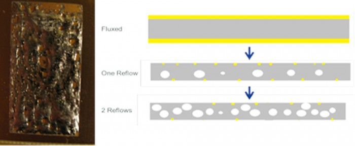
Figure 2. TIM1 is placed between the chip (or die) and the IHS.
Dr. Ron: I understand there have been some breakthroughs in reducing voiding, can you explain?
Jon: Historically, sTIMs were primarily used in LGA or PGA style packages. These packages were reflowed once to reflow the sTIM. Because of the benefits offered by sTIMs, there are efforts to find an optimal sTIM material and a process for packages that can survive multiple BGA reflow cycles, typically with a peak temperature of 240-250°C. With each subsequent reflow, traditional sTIM materials will exhibit void growth leading to poor thermal performance.
(InAg alloys show significant improvement compared to pure indium to reduce the void growth on subsequent reflows. See Figure 3.)
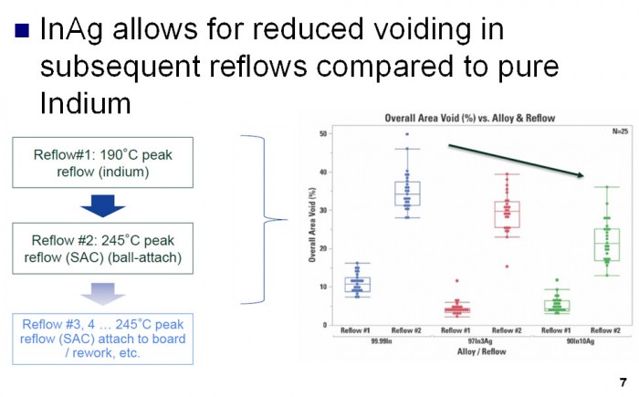
Figure 3. InAg TIM1s significantly reduce voiding compared to In TIM1s.
Jon: However, there are trade-offs to adding Ag to the solder joint. More Ag also means lower bulk thermal conductivity and a more rigid solder joint leading to reduced mechanical reliability. There is significant research underway to understand how different compositions of InAg wet to various surfaces and how they perform during reliability testing. High surface wetting, to minimize thermal contact resistance, is a critical TIM performance criterion. In addition, poor wetting can result in higher voiding, also leading to poor thermal performance. With the proper alloys selection, flux and process considerations sTIM can be adopted in Flip Chips BGA(FCBGA)style packages that will undergo multiple reflow cycles (see Figure 4).
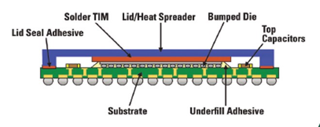
Figure 4. InAg sTIMs are a good fit for FCBGAs.
Folks,
Stay tuned for our next post on mTIMS1.5!
Cheers,
Dr. Ron