Folks,
A short time ago, I posted “Metal TIMs 101: Chapter 1” with Jon Major. Now it is time for Chapter 2!
Dr. Ron: Jon, what is TIM1.5?
Jon: TIM1.5 commonly refers to the interface between a bare die (a die without a lid) and a heat-sink or cold plate. Unlike TIM1, there is no heat spreader, and therefore the die is in direct contact with the cooling solution. See Figure 1. We refer to TIM1.5 as a system level TIM because the CPU/GPU/ASIC is already soldered onto a PCB, so the TIM is applied during system assembly (sometimes referred to as FATP (Final Assembly, Test and Pack)). Most TIM1.5 packages are considered lidless BGA style packages. TIM2 is also a system level TIM in many products.
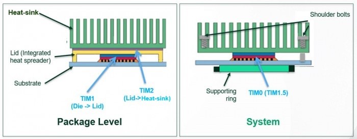
Figure 1. The application of TIM1, TIM2 and TIM1.5
Dr. Ron: When is TIM1.5 used?
Jon: Each interface in a thermal stack up adds thermal resistance. By eliminating the lid in a design, the total thermal resistance between the die and cooling solution is reduced in theory. However, the thermal interface material used in a TIM1.5 application plays a very important role in the performance of the overall thermal stack-up. Often, packages used in High Performance Computing (HPC) applications like GPUs, CPUs, or sometimes ASICs are designed without a lid to minimize thermal resistance, so a TIM1.5 material is then needed. Figure 2 shows a TIM1.5 covering four integrated circuit (IC)dies ready for the attachment of the heat-sink.
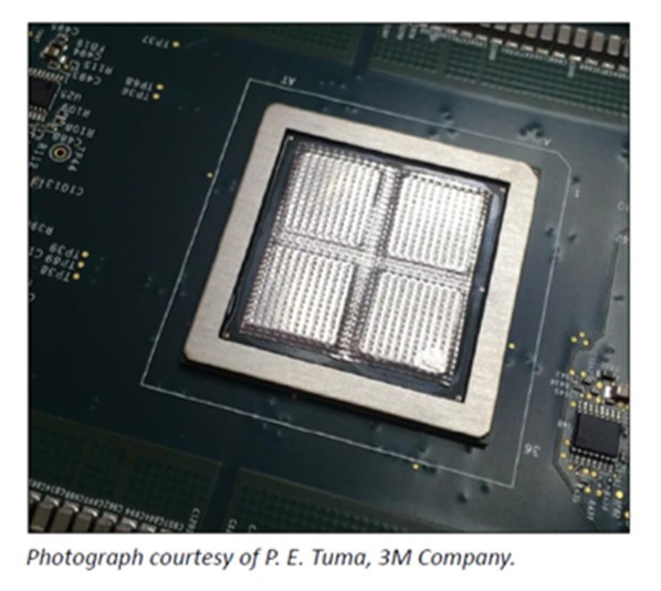
Figure 2. A TIM1.5 covering four IC die awaiting the application of the heat sink.
Dr. Ron: What are the challenges with TIM1.5?
Jon: The primary purpose of a TIM is to fill air gaps between a hot surface, such as the semiconductor die, and a cold surface, such as a heat-sink. Although metal-based TIMs have very high bulk thermal conductivity compared to polymeric based TIMs, thermal conductivity is not the sole criteria for selecting a TIM; the resistances at the interfaces of the TIM with the IC and the heat-sink are also important. So, for metal TIMs, it is important to have a metal solution with low thermal interface resistance. In addition, it is important to understand that a TIM that works well for one package style may not be ideal for others. Understanding how the TIM will be applied during system assembly is also critical. We see compressible metal TIMs, soldered TIMs, as well as liquid metal TIMs used in TIM1.5 applications. The challenges we help customers solve in TIM1.5 applications are primary focused around thermal resistance, surface wetting, surface flatness, surface roughness, clamping force, reflow temperature (if soldered), surface metallizations, void inspection methods, long-term reliability, as well as process implementation and optimization. Some customers prefer to use a solder TIM for TIM1.5, others compressible TIMs and many are interested in liquid metal TIMs because of its thin bondline thickness (BLT), excellent wetting, and low interfacial resistance.
Dr. Ron: Tell us about compressible metal TIMs used in TIM1.5.
Jon: Flat metallic foils have been used as a compressible TIM for several decades. Typically, they are indium metal or copper shims used in the telecom, military, or RF spaces, among others. In 2008, Indium Corporation patented a patterned metallic foil called “Heat-Spring®“, which is now a family of various alloys and pattern types designed to address a variety of high-performance applications, including TIM1.5, TIM2, burn-in, large area baseplates to cold plates for high power applications like IGBTs (insulated gate bipolar transistor) and SiC packages, as well as immersion cooling applications. The patterned metal helps to improve the thermal interface conductivity by eliminating air pockets between the TIM and heat-sink and the TIM and IC. Good thermal interface conductivity is a critical performance criterion for a compressible metal TIM.
Heat-Spring® is a soft metal alloy thermal interface material (SMA-TIM). It is a non-reflow compressible TIM that is very easy to apply and because it is patterned. It offers increased compliancy to the die and heat-sink surfaces compared to flat metallic foils. Pressure is concentrated on small contact areas in the pattern, causing plastic deformation and improving contact, reducing thermal resistance over time. When compressed between two surfaces, Heat-Spring® provides ultra-low thermal resistance even if those surfaces are warped, rough, or not coplanar. When used as a TIM1.5, Heat-Spring® provides a metal-based TIM solution without the need for complicated and costly system level reflow processes.
We recently developed an innovative new pattern called “HSx” that uses a new fabrication technique, offering increased compliancy for bowed or higher warpage dies (>150 μmof warpage) that also provides ultra-low thermal resistance with less pressure (30 psi) compared to our current patterns (HSD and HSHP (high profile)). See Figure 3.
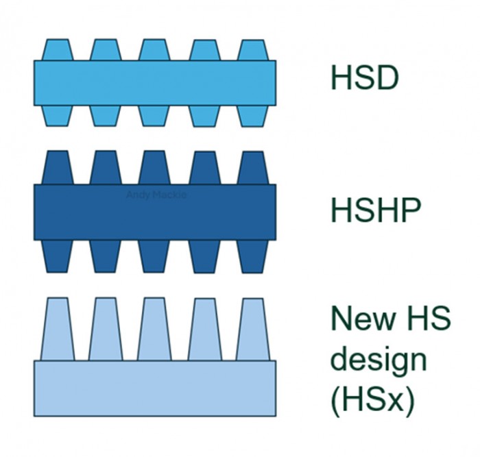
Figure 3. The different Heat-Spring® patterns.
Heat-Spring® compliancy improves with time and thermal cycling, referred to as “burn-in”. HSx has an especially short burn-in period and performance improves with thermal cycling. See Figure 4.
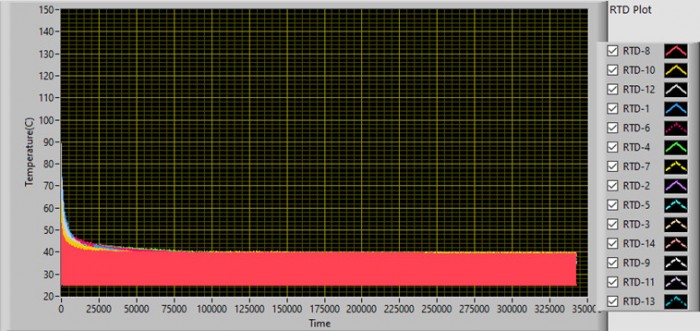
Figure 4. Power cycling of HSx, 0-600 Watts for 35,000 cycles. Tj reduces over time and stabilizes as seen above.
Customers continue to see warpage as a major challenge, given the CTE mismatch between the substrate and silicon chip. Thus, we developed the new pattern with warpage in mind. Because there is no backside metallization needed, HSx is an ideal TIM1.5 option for application where at least 30 psi of clamping force is available.
Dr. Ron: Why not use thermal grease? That would appear to handle warpage well and it has been around for a long time.
Jon: For some applications, thermal grease is a perfectly acceptable TIM, so long as the power is low. For such low-power density applications, grease often will perform just fine, but there is always a risk of “pump-out,” which happens when thermal cycling and CTE mismatches actually pump the thermal grease out of the TIM interface, often leading to thermal failure. Solid metal TIMs, however, are not subject to the pump-out failure mode and are ideally suited for high-power density components.
Dr. Ron: From Figure 5, copper has lower bulk thermal resistance. Why not use copper?

Figure 5. Thermal resistance of representative materials vs bondline thickness (BLT)
Jon: Although copper has an impressive bulk thermal conductivity of almost 400 W/mK, it is too hard and non-compliant to connect directly to a die as a TIM. It is not possible to apply enough pressure to plastically deform copper to fill in air gaps without crushing the die. The challenge of copper TIMs can be seen in Figure 6. Note the high-gap thermal resistance of copper as a function of pressure compared to indium. Figure 5 also shows the very high thermal resistance of thermal grease.
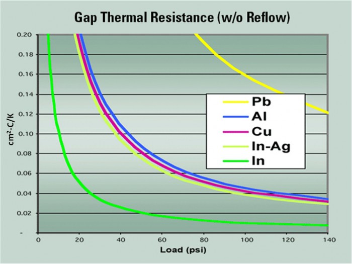
Figure 6. Thermal gap resistance of representative metals as a function of pressure.
Dr. Ron: How does Heat-Spring® work in immersion cooling?
Jon: Heat-Spring® is a proven TIM in both direct-to chip (DTC) and immersion cooling applications. It’s rather common to see Heat-Spring® used as a TIM in immersion systems. Unlike thermal greases or popular polymer phase change materials (PCMs), Heat-Spring®s will neither dissolve nor contaminate standard organic or fluorinated dielectric immersion fluids. It’s easy to install either as a TIM2 or TIM1.5 – simple place the Heat-Spring® and clamp the heat-sink or cold plate to the assembly. We also have new novel ways of applying the Heat-Spring®, which further reduces contact resistance. We are looking forward to introducing these new methods to industry in the near future.
Dr. Ron: Are heat-springs recyclable?
Jon: Yes! Indium-based Heat-Spring®s are 100% reclaimable and have an enormous benefit to sustainability programs. Rather than sending material to a landfill, we will buy back used indium, and many other metals, which can be used again.
Dr. Ron: Jon, thanks. Let’s discuss some other TIM solutions to thermal management challenges in the near future
Jon: You bet!