Autonomy, combined with greater customer demand for connectivity and media capability with vehicles, has caused the number of electronics within the automobile to dramatically rise. Or, as some have called it, making the automobile a "computer on wheels." Is it any wonder that there is tremendous interest and growth in electronics and software platforms and designs for automobiles? All these demands require faster processor times and greater capability from automotive electronics.
These higher electronic processor speeds produce higher temperatures in the electronic components. For automotive electronics, the higher temperatures raise concern when considering the high thermal load and harsh conditions that exist, especially under the automobile’s hood. Added to this concern is the duration that the electronics need to survive—10 years plus, and the extremely high- reliability required in this new world of autonomous automobiles.
As stated earlier, the clock speeds and computing power of integrated circuits is increasing, resulting in higher computer temperatures. When the integrated circuit is mounted in a bottom-terminated component (BTC) that has been assembled with significant voiding, the heat generated by the integrated circuit cannot be dissipated effectively. This situation exists because the air in the void is a very poor conductor of heat. Although the total void area affects the total amount of heat transmitted, in some cases it can be worse to have all of the void area in one spot as this situation can create a hot spot in the component.
There is no agreement as to what is an acceptable amount of voiding, and there is no IPC specification for it. In the past, some have suggested that voiding in the 25% range is acceptable. However, 10% or lower is now often the target due to integrated circuits increasing computing power, thus raising the operating temperatures and increasing concern for reliability.
One variable affecting voiding is particle size. As components decrease in size, the solder required to attach them also decreases. The reduced stencil apertures that provide the smaller deposits challenge the stencil printing process. The conversation then begins to lean towards investigating the use of finer powder solder pastes. The concern however, is there a trade-off? Finer powder solder pastes mean more exposed surface area, and more surface area relates to more surface oxide which may increase the amount of voiding. The following DOE was performed to examine the effect of powder size on voiding:
Solder Paste Flux Vehicles (No-Clean)
- Paste 1 ROL0
- Paste 2 ROL1
Alloy
- SAC305
Powder Size
- Type 3 (25-45 micron)
- Type 4 (20-38 micron)
- Type 4.5 (20-32 micron)
- Type 5 (15-25 micron)
- Type 6 (5-15 micron)
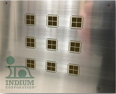
Figure 1
Stencil (Figure 1)
- 4mil-thick laser cut
- Window pane thermal pad (2x2)
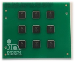
Figure 2
Test Vehicle (Figure 2)
- 9 QFNs per board
- Surface finishes:
- CuOSP
- ENIG
- Imm Sn
- Imm Ag
- 2 boards per each set of parameters
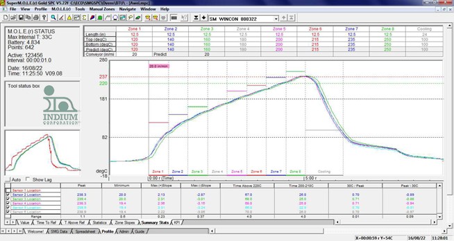
Figure 3
Reflow Profile (figure 3)
- Ramp to Peak Air and N2
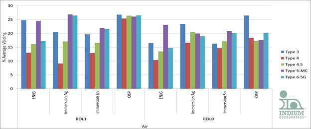
Figure 4. Results
Results
- Type 4 provided best results (same with N2)
- CuOSP less affected by particle size
- ROL0 performed better than ROL1

