A quick trip to discuss roadmapping with one of the world’s top processor manufacturers, and a visit to discuss Pb-free power die-attach materials, left me with a few hours to spare at LAX.
This time around I was trying to work out how much package-on-package (PoP) solder paste we would expect to see for a waferlevel CSP (WL-CSP) or a BGA dipped to half height. The need for some deep thought was driven by a customer who asked at what point a PoP dipping paste needs to go from a type 4 to type 5, 6, 7 and so on (however you define them), based on the PoP/CSP pitch or ball diameter. Good question.
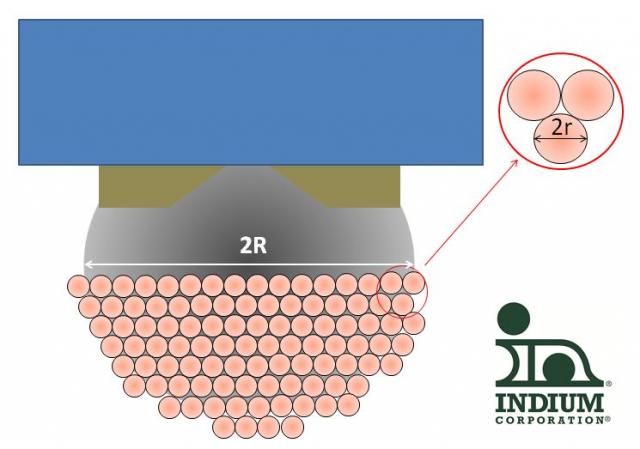
To start with, in order to get consistent quantities of paste on each sphere, the PoP paste metal loading needs to be well below the point at which rheopectic behavior can expect to be seen (that is, much less than 50% by volume of solder powder metal). By doing this, you pretty much guarantee a “monolayer” of solder paste powder particles (radius r) coating the CSP or BGA sphere (radius R). Figure 1 shows the kind of result that is typical for a good paste: in this instance our halogen-free PoP paste Indium 9.88-HF.
If the metal loading is too high, even at time zero, you will start seeing large variations in the amount of PoP solder paste adhering to the surface of each sphere (bump), even on adjacent spheres: the small amount of paste that is picked up during the dipping process adheres to the main solder sphere in uneven clumps. This is why standard type 4 printing solder pastes just don’t work in PoP applications: not only is the particle size too big – the rheology is all wrong.
If R>>r, then a reasonable first order approximation is that you can treat the sphere surface as planar and so model the number of solder particles based on a series of hexagonally close-packed particles (Figure 2 gives the definitions).

Figure 2: Definitions for the PoP paste dipping process
Using the same model of solder powder particle size as in the discussion on waferbumping paste, you can calculate a couple of potentially useful things:
i/ The maximum number of solder powder particles on each solder sphere (bump)
ii/ The mass of solder paste adhering to each soldersphere
The first (i/) is useful for establishing the inherent variability due to the finite size of the solder powder, and I’m going to suggest another Mackie rule of thumb of a minimum 150 solder powder particles per solder bump, based on the maximum allowed particle size (diameter). The table below gives the result of this rather simplistic analysis:

Table: Effect of Package Bump Diameter on Solder Paste Type Needed
A 400micron bump should therefore be fine even with a type 3 dipping paste, whereas a 200micron bump will need a type 5 paste.
I look forward to someone proving this wrong. The second (ii/) is helpful, because we can easily use it to test the theoretical mass of PoP dipping paste against what we actually find. Note that this is just simple geometry: it doesn't tell us how much paste is really needed to resolve issues such as the 60 - 90micron bowing we are hearing about from our customers, even with the more rigid PoP packages currently available.
Cheers! Andy


