My friend and colleague Chris Nash and I were recently discussing some puzzling results for low dip height found during testing of package-on-package (PoP) materials. The findings will be of interest to everyone who uses a dipping process in both SMT and flip-chip assembly. Firstly, a little background. Many of you will be familiar with the two types of dipping tray used in both PoP and flip-chip assembly:
Linear Type – Although the doctor blade in a system of this type is usually the moving component, there are some tools where the dip tray itself moves from side to side under a fixed “blade” or reservoir. EB Datacon flip-chip dipping equipment, for example, may be of either type.
Advantages have been claimed for both types of system, but the rotary type seems to be winning out over the linear type for very precise dip depth control. That said, linear seems to be much more common. Why should this be?
One clue that we recently discovered is that the dip depth for a linear system is always less than the designed depth: whether the fluid in it be a flux or a dipping solder paste. The assumption is that the depth of flux in the linear dip tray is exactly the same as the design height (below).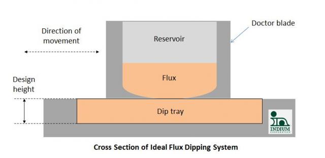
However, as evidenced by both visual inspection of the solder ball / flip-chip bump dip height, and also by direct measurement of the fluid in the dip tray, the actual flux or paste dip height is always less than the design height (below). Why should this be? 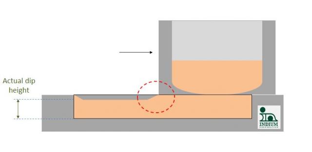
The answer can probably be found in reference to the concept of a boundary layer (red circle above): a layer of material immediately adjacent to a surface that is either completely immobile (static boundary layer) or moving at a velocity less than in the bulk of the moving fluid. With no boundary layer, there would be no drag (fluid frictional forces) and of, course, that is why golf balls have dimples: so that the boundary layer is kept mostly beneath the outer surface of the ball, to reduce drag. This principle has also been adopted for some squeegee blades.
The reduction in height is of the order of 10-20microns, as closely as we can tell with the measurement systems available. So, for a 200micron dip depth, this will only lead to an error of -5 or -10% in the actual dip height.
Since most dipping materials are thixotropic, there is the added complication of time dependence of the material’s rheology. The fastest way to reach the equilibrium dip depth is to use a very fast movement of the doctor blade system relative to the dipping tray, although this will almost inevitably increase the prevalence of bubbles.
Again, the linear system is most commonly seen for most PoP and flip-chip dipping applications, but it clearly has its limitations, as we will discuss in part II.
I welcome your comments.
Cheers! Andy

